Question 11
Find the front view, top view and side view of each of the following solids, fixing its orientation with respect to the vertical, horizontal and side planes: cube, cuboid, parallelepiped, cylinder, cone, prism, and pyramid. If needed, see the next problem for clues.
- A 3D solid can be visualised in two dimensions by projecting it onto three mutually perpendicular reference planes:
- Front View: What is seen when looking directly at the solid from the front (projected onto the vertical plane).
- Top View: What is seen when looking directly down from above (projected onto the horizontal plane).
- Side View: What is seen when looking directly from the side (projected onto the side/profile plane).
- For standard shapes, we assume standard orientation with the base resting on the horizontal plane and the main axis vertical.
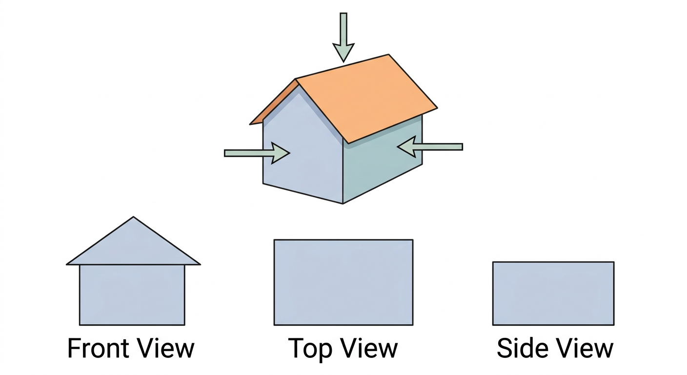
Step 1 · Viewing Directions and Reference Planes
When an object is placed in front of reference planes:
- Front view is observed looking directly from the front.
- Top view is observed looking directly from above.
- Side view is observed looking directly from one side.
Step 2 · Views of a Cube
For a cube of side length aligned with the viewing planes: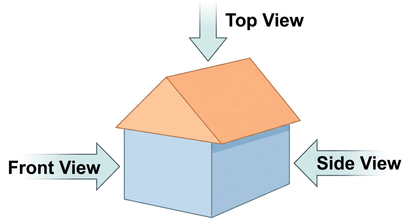
- Front view: Square of dimensions
- Top view: Square of dimensions
- Side view: Square of dimensions
Step 3 · Views of a Cuboid
For a cuboid with length , breadth , and height :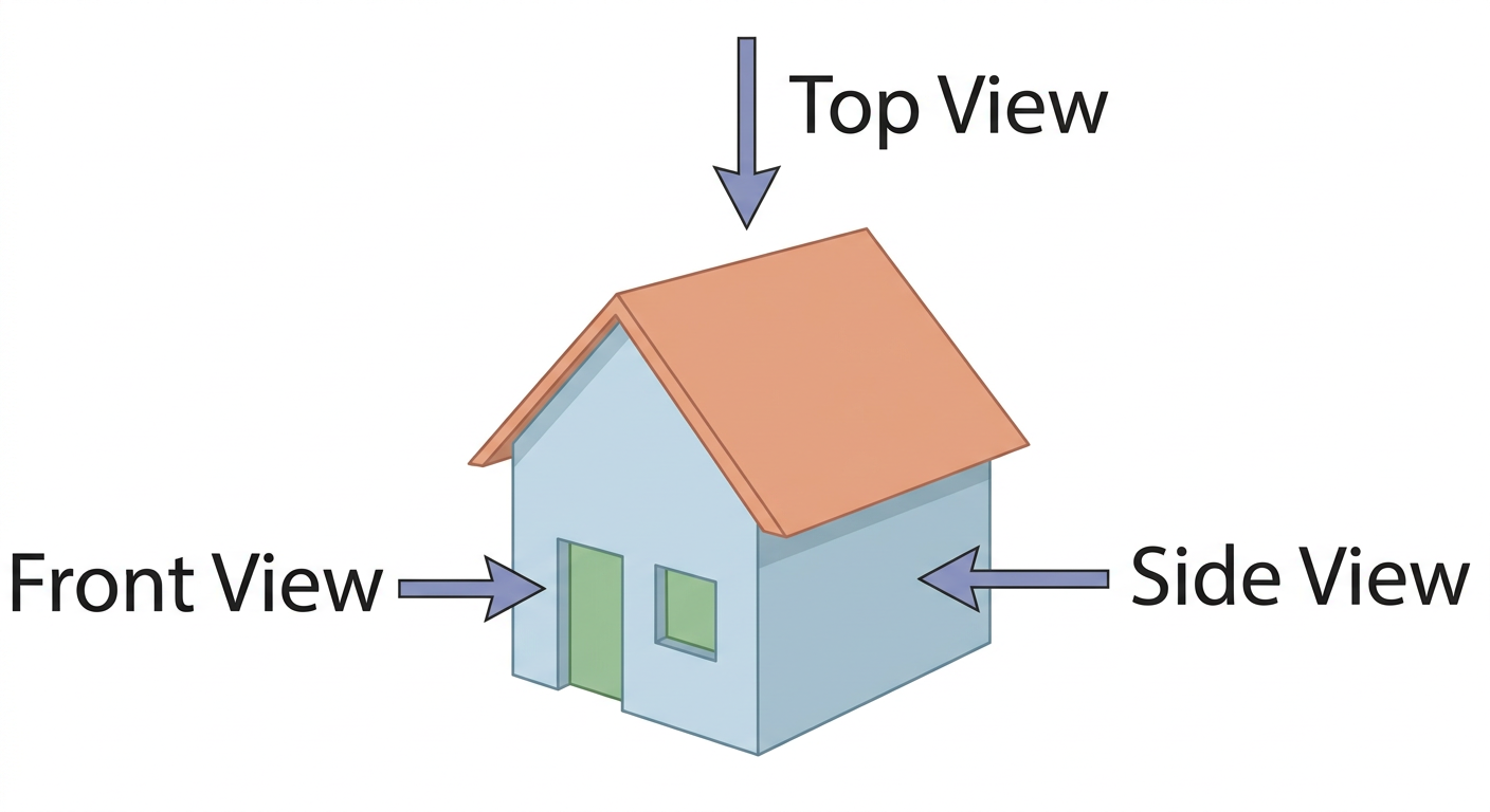
- Front view: Rectangle of dimensions
- Top view: Rectangle of dimensions
- Side view: Rectangle of dimensions
Step 4 · Views of a Parallelepiped
A parallelepiped has six faces that are all parallelograms: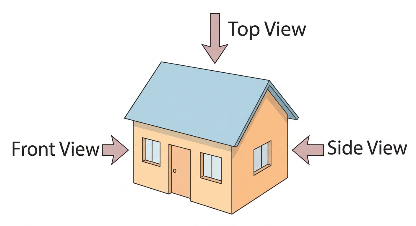
- Front view: Parallelogram
- Top view: Parallelogram
- Side view: Parallelogram
Step 5 · Views of a Cylinder
For an upright cylinder with its circular base on the horizontal plane and vertical axis: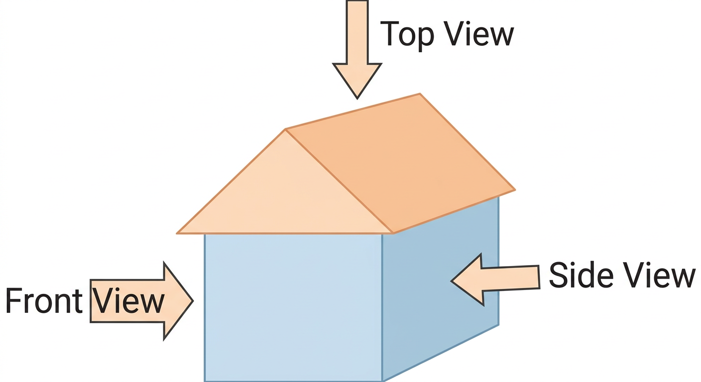
- Front view: Rectangle (width diameter, height cylinder height)
- Top view: Circle
- Side view: Rectangle (identical to front view)
Step 6 · Views of a Cone
For an upright cone with its circular base resting on the horizontal plane and apex at the top: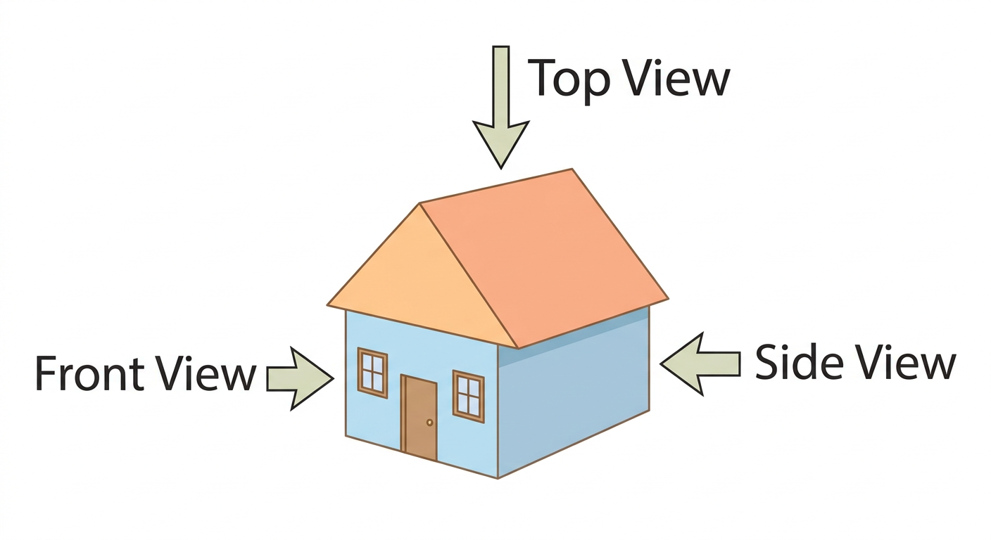
- Front view: Isosceles triangle
- Top view: Circle with a central point (apex)
- Side view: Isosceles triangle
Step 7 · Views of a Prism (Square Base)
For a right prism with a square base resting horizontally and axis placed vertically: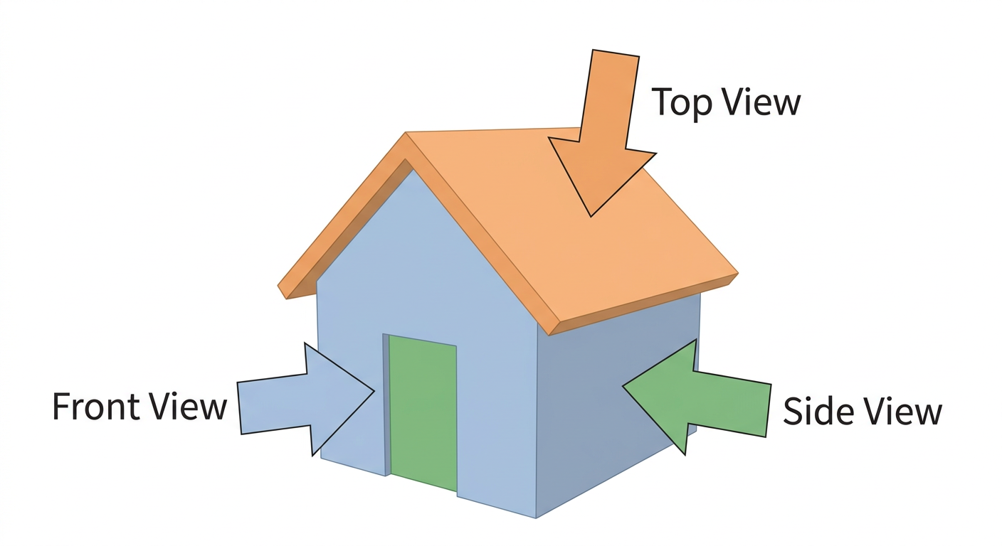
- Front view: Rectangle
- Top view: Square
- Side view: Rectangle
Step 8 · Views of a Pyramid (Square Base)
For a pyramid with a square base resting horizontally and axis placed vertically: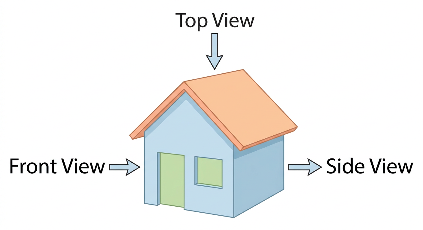
- Front view: Isosceles triangle
- Top view: Square with diagonals intersecting at the center
- Side view: Isosceles triangle
(a) Cube: Front view: square, Top view: square, Side view: square.
(b) Cuboid: Front view: rectangle, Top view: rectangle, Side view: rectangle.
(c) Parallelepiped: Front view: parallelogram, Top view: parallelogram, Side view: parallelogram.
(d) Cylinder: Front view: rectangle, Top view: circle, Side view: rectangle.
(e) Cone: Front view: isosceles triangle, Top view: circle with center dot, Side view: isosceles triangle.
(f) Prism (square base): Front view: rectangle, Top view: square, Side view: rectangle.
(g) Pyramid (square base): Front view: isosceles triangle, Top view: square with diagonals, Side view: isosceles triangle.
- Top View Apex Details: Forgetting to show the apex in the top view of a cone (a center point) or a square pyramid (two intersecting diagonals connecting opposite vertices).
- Curved Surface Views: Mistaking the front or side view of a vertical cylinder as curved; projected orthogonally, its outline is a flat rectangle.
- Orientation Assumptions: Assuming views remain identical regardless of orientation; rotating a cylinder onto its curved side turns its front view into a circle.
More questions in FIO
Draw the initial few steps (at least till Step 2) of the shape sequence that leads to the Sierpinski Triangle.
Find the number of holes, and the triangles that remain at each step of the shape sequence that leads to the Sierpinski Triangle.
Find the area of the region remaining at the th step in each of the shape sequences that lead to the Sierpinski fractals. Take the area of the starting square/triangle to be 1 sq. unit.
Draw the initial few steps (at least till Step 2) of the shape sequence that leads to the Koch Snowflake.
Find the number of sides in the step of the shape sequence that leads to the Koch Snowflake.
Find the perimeter of the shape at the step of the sequence. Take the starting equilateral triangle to have a sidelength of 1 unit.
Figure it Out
- Which of the following are the nets of a cube? First, try to answer by visualisation. Then, you may use cutouts and try.
A cube has 11 possible net structures in total. In this count, two nets are considered the same if one can be obtained from the other by a rotation or a flip. For example, the following nets are all considered the same —
Find all the 11 nets of a cube.
Draw a net of a cuboid having sidelengths:
(i) , , and
(ii) , , and
Observe the front view, top view and side view of the different lines in Fig. 4.6. Is there any relation between their lengths?
Find the front view, top view and side view of each of the following solids, fixing its orientation with respect to the vertical, horizontal and side planes: cube, cuboid, parallelepiped, cylinder, cone, prism, and pyramid. If needed, see the next problem for clues.
Match each of the following objects with its projections.
Draw the top view, front view and the side view of each of the following combinations of identical cubes.
Imagine eight identical cubes, glued together along faces to form the letter 'C'.
Which solid corresponds to the given top view, front view, and side view?
Solids to choose from:
Using identical cubes, make a solid that gives the following projections:
Find the number of cubes in this stack of identical cubes.
What are the different shapes the projection of a cube can make under different orientations?
In addition to the 5 ways shown in Fig. 4.8, are there any additional ways of gluing four cubes together along faces? Can you visualise and draw these as well?
Draw the following figures on the isometric grid.
[Hint: It may be useful to determine whether the edge to be currently drawn — say, along the height — goes from down to up or up to down. Accordingly, draw the line segment on the grid either in the direction of the height axis or opposite to it.]
Is there anything strange about the path of this ball? Recreate it on the isometric grid.
[Hint: Consider a portion of this figure that is physically realisable and identify the 3 primary directions.]
Observe this triangle.
(i) Would it be possible to build a model out of actual cubes? What are the front, top, and side profiles of this impossible triangle? (ii) Recreate this on an isometric grid. (iii) Why does the illusion work?